One of the very first examples for an MCU or SoC usually involves the famous ‘Blinky‘ example, where an LED is pulsed on and off with a fixed delay. This is actually a lot more complicated than the ‘Pushy‘ example which we looked at in the first installment of this series. The reason for this is that there’s actually quite a story behind a simple call to delay() or its equivalent.
The reason for this is that there are many ways to implement a delay function on a microcontroller (MCU), each of which comes with their own advantages and disadvantages. On an STM32 MCU, we get to choose between essentially an active delay (while loop), one implemented using the SysTick timer and using one of the peripheral timers. In the latter two cases we also have to use interrupts.
In this article we’ll take a look at all three approaches, along with their advantages and disadvantages.
In Arm MCU architectures, generally the same Cortex-M processor core is used within the same family of MCUs by a manufacturer such as ST Microelectronics (‘ST’). This core is connected via a variety of AMBA (Advanced Microcontroller Bus Architecture) buses, with AHB being the fast bus. AHB connects the core to all peripherals that need the low latency and speed, such as RAM, ROM and display controllers.
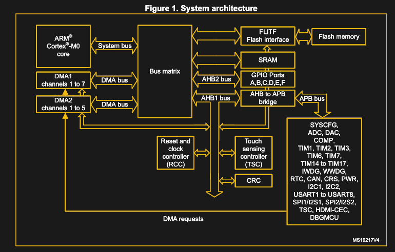
Meanwhile the slower APB connects peripherals that are fine with less bandwidth and lower speeds, which includes the general-purpose IO (GPIO) banks, I2C, timers, USARTs and SPI peripherals. In the Pushy example, the processor core would constantly query the GPIO peripheral’s incoming data register (GPIO_IDR) and write into the outgoing data register (GPIO_ODR) depending on those input values.
In the case of the Blinky example, we remove the active polling of the GPIO_IDR that was used to read the button input, instead relying on the delay function that is added. Whenever we return from this blocking delay function, we toggle the GPIO_ODR bit, which causes the LED that is connected on that pin to be lit or not.
The code example as implemented using my Nodate framework thus becomes:
.gist table { margin-bottom: 0; }
| #include <gpio.h> | |
| #include <timer.h> | |
| int main () { | |
| // Initialise. | |
| Timer timer; | |
| //const uint8_t led_pin = 3; // Nucleo-f042k6: Port B, pin 3. | |
| //const GPIO_ports led_port = GPIO_PORT_B; | |
| //const uint8_t led_pin = 13; // STM32F4-Discovery: Port D, pin 13 (orange) | |
| //const GPIO_ports led_port = GPIO_PORT_D; | |
| //const uint8_t led_pin = 7; // Nucleo-F746ZG: Port B, pin 7 (blue) | |
| //const GPIO_ports led_port = GPIO_PORT_B; | |
| const uint8_t led_pin = 13; // Blue Pill: Port C, pin 13. | |
| const GPIO_ports led_port = GPIO_PORT_C; | |
| // Set the pin mode on the LED pin. | |
| GPIO::set_output(led_port, led_pin, GPIO_PULL_UP); | |
| GPIO::write(led_port, led_pin, GPIO_LEVEL_LOW); | |
| while (1) { | |
| GPIO::write(led_port, led_pin, GPIO_LEVEL_HIGH); | |
| timer.delay(1000); | |
| GPIO::write(led_port, led_pin, GPIO_LEVEL_LOW); | |
| timer.delay(1000); | |
| } | |
| return 0; | |
| } |
This example defines a few presets for different boards, with here the ‘Blue Pill’ (STM32F103C8) version used. We won’t cover the GPIO module here again, as the used GPIO functions in this example were already explained in the first article in the series. Feel free to have a look at it if you need a refresher, though.
Our focus will be on the Timer module instead, the way its delay() function is implemented, as well as the two alternate approaches.
A completely serviceable, functional, and reasonably accurate delay feature can be implemented in a bare-metal environment using nothing more than a humble while() loop. This exploits the discrete nature of processor cycles in combination with knowing the current system clock. Essentially this means converting the desired delay to processor time and counting down (or up) to that interval.
Assume the MCU (SysClock) is clocked at 48 MHz. If we want to delay with microsecond resolution, we need to multiply the μs interval value with 48 to get the target number of clock cycles we wish to wait. Naturally, each iteration of the while() loop takes more than one clock cycle, so we then have to divide the number of clock cycles by the duration of a loop iteration. Say it takes 4 clock cycles for one loop iteration, we get:
int count = (usecs * 48) / 4;
while (int i = 0; i < count; ++i) {
    count--;
}
Obviously, this is a rather easy way to implement a delay function, once one has calculated the appropriate parameters. As with many things in life, when something is this easy, it has to come with a whole list of gotchas. In the case of this delay function one doesn’t get disappointed in that regard.
First and foremost is its lack of accuracy. Even if we didn’t use integer values to calculate the appropriate clock cycle interval, there is still the unavoidable weakness in that this function fully runs on the (single) processor core. The moment a single interrupt occurs (e.g. from a timer, USART, I2C or GPIO peripheral), it will throw off the count by how many cycles it takes to process that interrupt and return to the main task execution.
The fact that this is an active delay, which fully occupies (in other words blocks) the processor further means that it does not work for a multitasking environment. In effect, this is the kind of delay function you really only wants to use as a quick-and-dirty throw-away function during testing or debugging.
The Cortex-M core has a few standard peripherals as well that are integrated directly into this core. These are covered in the Programming Manual (PM) for each MCU family, e.g. for STM32F0. These so-called Core Peripherals include the SysTick Timer (STK, or SysTick), Nested Vectored Interrupt Controller (NVIC) and System Control Block (SCB). Of these, NVIC is as the name implies essential for registering and handling interrupts.
The SysTick timer is a fairly simple timer, which can essentially count down from the set value to zero. While this doesn’t sound amazing, it uses the processor clock, this means that it’ll not be affected by interrupts and other events that would interrupt the active delay timer which we looked at earlier.
As we saw in the Blinky example code, we first create an instance of the Timer class. This sets up a few items in the constructor of the Timer class:
.gist table { margin-bottom: 0; }
| Timer::Timer() { | |
| // Set reload register to generate an interrupt every millisecond. | |
| SysTick->LOAD = (uint32_t)((SystemCoreClock / 1000) – 1); | |
| // Reset the SysTick counter value. | |
| SysTick->VAL = 0UL; | |
| // Set SysTick source and IRQ. | |
| SysTick->CTRL = (SysTick_CTRL_CLKSOURCE_Msk | SysTick_CTRL_TICKINT_Msk); | |
| } |
Most importantly, we set the value to countdown from. This uses the global SystemCoreClock value with the current system clock in Hertz, dividing it to create the equivalent value for 1 millisecond. This is written into STK_RVR (called LOAD in CMSIS).
We also pick the clock source to use with the SysTick peripheral, which here is ‘Processor clock’. Finally, we enable the generation of interrupts whenever the count reaches zero. With all of this configured, the delay() function can be used:
.gist table { margin-bottom: 0; }
| static volatile uint32_t DelayCounter; | |
| void SysTick_Handler() { | |
| DelayCounter++; | |
| } | |
| void Timer::delay(uint32_t ms) { | |
| // Enable the SysTick timer | |
| SysTick->CTRL |= SysTick_CTRL_ENABLE_Msk; | |
| // Wait for a specified number of milliseconds | |
| DelayCounter = 0; | |
| while (DelayCounter < ms); | |
| // Disable the SysTick timer | |
| SysTick->CTRL &= ~SysTick_CTRL_ENABLE_Msk; | |
| } |
As mentioned, every time the SysTick timer reaches zero, it generates an interrupt. We reimplemented the interrupt handler SysTick_Handler(), so that on each call we can increment a global counter variable. The delay function itself starts the SysTick timer and waits for the global counter variable to reach the target value that was passed to it as a parameter. After completing this, the SysTick timer is disabled again and the function returns.
The advantages over an active delay loop should be fairly obvious: by using a hardware peripheral in the Cortex-M core, we are assured of good accuracy. With a change such as the use of the target interval as the STK_RVR value for example, we could further reduce any active waiting. SysTick can also be used for a central system timer, keeping track of uptime and intervals. Here one would quickly stray into the area of full-blown embedded operating systems, however.
Although somewhat more complicated than a simple while() loop, there’s no good reason to choose a blocking delay instead of the far superior SysTick method.
While the SysTick timer is convenient in that it’s universally present in STM32 MCUs and exceedingly simple to use, this simplicity also comes with some disadvantages. Not the least of which is the fact that there is only a single SysTick peripheral. Fortunately, most STM32 MCUs come with a selection of additional timer peripherals that can also be used for adding delay functions, depending on one’s needs.
The General-purpose timer cookbook for STM32 microcontrollers (AN4776) document from ST gives an example of how to implement a basic delay loop in section 1.3.2, using the TIM6 peripheral:
.gist table { margin-bottom: 0; }
| #define ANY_DELAY_RQUIRED 0x0FFF | |
| /* Hardware-precision delay loop implementation using TIM6 timer | |
| peripheral. Any other STM32 timer can be used to fulfill this function, but | |
| TIM6 timer was chosen as it has the less integration level. Other timer | |
| peripherals may be reserved for more complicated tasks */ | |
| /* Clear the update event flag */ | |
| TIM6->SR = 0 | |
| /* Set the required delay */ | |
| /* The timer presclaer reset value is 0. If a longer delay is required the | |
| presacler register may be configured to */ | |
| /*TIM6->PSC = 0 */ | |
| TIM6->ARR = ANY_DELAY_RQUIRED | |
| /* Start the timer counter */ | |
| TIM6->CR1 |= TIM_CR1_CEN | |
| /* Loop until the update event flag is set */ | |
| while (!(TIM6->SR & TIM_SR_UIF)); | |
| /* The required time delay has been elapsed */ | |
| /* User code can be executed */ |
Naturally, the fun thing with STM32 timer peripherals is that there are so many to choose from. Each of them falls within a certain complexity range, which scales roughly from ‘fairly basic’ to ‘everything and the kitchen sink’. The advanced timers are the ones you want to use for pulse-width modulation (PWM) and more complex tasks, leaving one with a few basic timers, the exact number of which depends on the MCU.
While we could count on the SysTick timer always being present, other timer peripherals are less predictable and require more effort to set them up. This makes them more suitable for specialized tasks, rather than implementing a delay loop. Which is not to say that one couldn’t do it, yet the benefits would have to be apparent.
With all of that said, I hope that this gives a clearer picture of delay loops on STM32 MCUs. These are hardly all the options either, with some enterprising people even using the built-in debugging hardware (e.g. Data Watchpoint Trigger, DWT) for timer functionality. Yet portability and ease of use should also be considerations.
At the end of this article, I would like to reiterate again that despite the common portrayal of the ‘Blinky’ example, there is actually a lot that goes into making it work.
Bare-Metal STM32: Blinky And The Secret Of Delay Functions
Source: HackADay