The lingua franca of electronic design is the schematic. I can pick up a datasheet written in Chinese (a language I do not read or speak) and usually get a half-decent idea of what the part is all about from the drawings. Unfortunately, even as my design experience has grown over the years, I haven’t quite learned to think in schematics — I need to see it on paper (or on a screen) to analyze a circuit. Whether it’s literally on the back of an envelope or sketched in the condensation on the shower stall, actually drawing a design or idea makes a huge difference in being able to understand it. And, if you’ve ever tried to explain a circuit without a schematic — in an on-line forum or over the phone, for instance — you know how difficult it is.
So, given the importance of the schematic for design and communication, you’d think choosing a tool to draw them would be an easy task. Not so. There are dozens of choices, from dedicated schematic drawing programs to using the schematic-capture facilities of simulation or PCB design tools, or even old-fashioned pencil-and-paper and its modern equivalents. Each one has its pros and cons, and may be better suited to one specific application, but you have to choose something.
So, readers of Hackaday, what do you use to convey your electronic design ideas to the world?
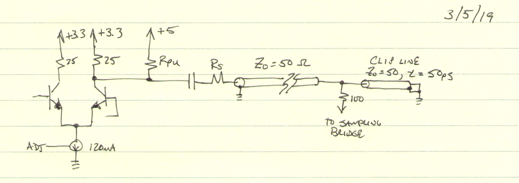
The simplest approach is just to take up pen and paper and get to it. The field of electronics obviously pre-dates modern computer UI’s, so there is a rich history of hand-drawn schematics; just open any book from before the integrated circuit era to see some. This approach offers the ultimate flexibility – you can generally use anything at hand to draw your circuit, from your antique oak drafting table and Rapidograph pens to a stick in the sand. The downside is that if you’re not an artist (or skilled drafting technician), your schematics will certainly reflect this, as mine do. But, it’s easy, quick, and portable.

The next step up is virtual pen-and-paper: a general-purpose drawing program. Although I admit to drawing a few schematics in Paintbrush under Windows several decades ago, your best bet is probably a vector drawing program. I know it shows my *nix graybeardedness, but my go-to drawing program is xfig. There are many more modern alternatives, including Dia and Inkscape, while readers can certainly recommend tools specific to other platforms. A convenient way to use a package like this is to build up a library of symbols that you commonly use. This gives you flexibility to draw them as you like: you’re free to draw your resistors as little boxes, while I’ll keep my squiggles. The downside is that you’re basically starting from scratch, although some packages may have electronics symbol libraries you can leverage (xfig does, but I don’t like their look).
One disadvantage of either approach is that you can’t generate netlists to import into simulation or PCB layout tools, but if you’re not going to use either one, this doesn’t matter.
Stepping up from general-purpose drawing tools, we come to packages dedicated to schematic drawing. The first one of these I ever encountered was XCircuit, another relic from the good old UNIX days. The stated goal of this program is to produce quality output for publication, as opposed to schematic capture for further processing. A little searching also turns up TinyCAD, which does output netlists, but also claims high-quality output suitable for publication. Learning one of these tools never quite seemed worth the investment, since they are targeted at such a specific niche purpose. Every other tool category I’ve considered has a secondary use — for example, time spent learning Inkscape to draw schematics could be leveraged to use the program for any number of purposes. Maybe these tools are perfect for my use case, but I just haven’t given them a shot?
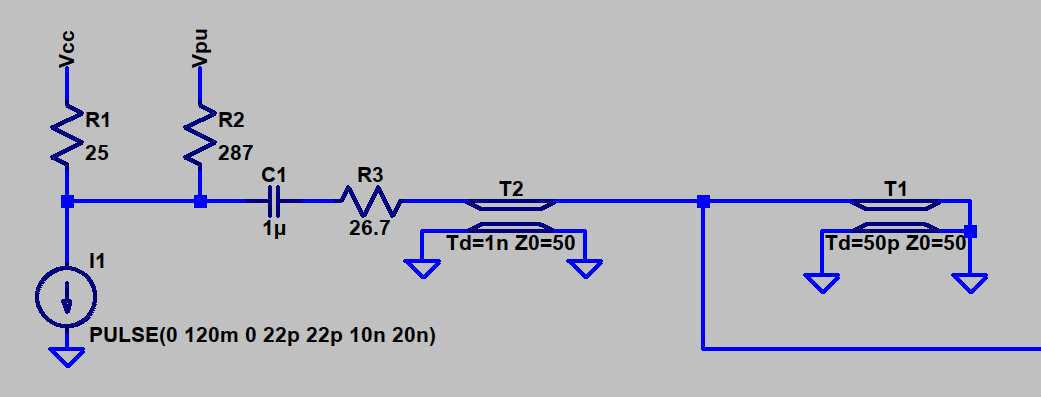
Modern circuit simulators come with relatively decent user interfaces, although each has its quirks. Conventional wisdom is that like PCB layout programs, you carefully choose one that best suits your needs, then complain loudly about it. Of the several simulation tools I’ve used, I’ve logged by far the most hours using LTspice, the free (gratis, not libre) simulation tool from Linear Technologies (now part of Analog Devices). If you need to simulate your circuit anyway, you can sometimes kill two birds with one stone by using the schematic from your simulator for publication. Of course, for simulation purposes, you may include some parts (parasitic components, for example), that won’t be listed in the BOM, and substitute voltage or current sources for whole subsections of the design. These changes cause the simulation schematic to diverge from the published one, so you may end up drawing it twice anyway.
One advantage I’ve found to this approach is that all the components have presumably been drawn to be “compatible” — in the same style and scale.

CAD programs for PCB design also feature schematic capture facilities you can leverage to generate diagrams for publication. I happen to use Eagle, although I know there are a lot of KiCAD types out there. Either one, or any number of alternatives, would provide the same functionality. There is typically a closer match between the schematics captured for PCB layout and publication than those used for simulation, although sometimes it’s useful to show more information than you need to design a PCB — a simplified diagram of the internals of an IC, for example. The biggest disadvantage I have found is that symbols from different libraries may be drawn in a different style or at a different scale, making for an ugly schematic output. As a result, I’ve ended up re-creating my own library of symbols, which also eliminates any licensing concerns (I care more about the license of designs I create than of the tools I’m using).
To Cloud or Not to Cloud?
All the tools I’ve mentioned above are traditional desktop applications, which I prefer. Of course, there are now cloud-based tools in each of the categories. I haven’t explored this space very well, although I’m certainly aware of circuitlab, which is the preferred tool for schematics on Electronics.StackExchange, and the Falstad circuit simulator, which sees occasional use on hackaday.io. I’m sure there are other tools out there, but my reluctance to adopt a cloud-based workflow has kept me from fully investigating the options. Maybe I’ve missed exactly what I’m looking for?
OK, Hackaday, what tools do you use to produce schematics? Are there tricks that make one particular tool easier to use for this purpose? Does everyone end up with a mishmash of tools like I have, or have people figured out how to get all the functionality they need from just one? Let us know in the comments below.
Ask Hackaday: How Do You Draw Schematics?
Source: HackADay