In the last Circuit VR we looked at some basic op amp circuits in a simulator, including the non-inverting amplifier. Sometimes you want an amplifier that inverts the signal. That is a 5V input results in a -5V output (or -10V if the amplifier has a gain of 2). This corresponds to a 180 degree phase shift which can be useful in amplifiers, filters, and other circuits. Let’s take a look at an example circuit simulated with falstad.
Last time I mentioned two made up rules that are good shortcuts for analyzing op amp circuits:
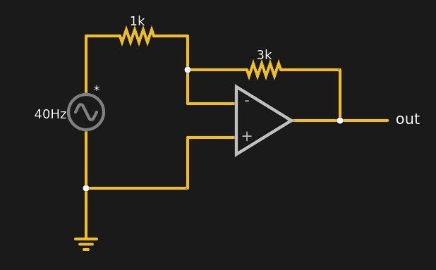 As a corollary to the second rule, you can easily analyze the circuit shown here by thinking of the negative (inverting) terminal as a virtual ground. It isn’t connected to ground, yet in a properly configured op amp circuit it might as well be at ground potential. Why? Because the + terminal is grounded and rule #2 says the op amp will change conditions to make sure the two terminals are the same. Since it can’t influence the + terminal, it will drive the voltage through the resistor network to ensure the – terminal is at 0V.
This virtual ground idea makes the analysis of the circuit simple. You can see on the simulation that the amplifier has a gain of 3. So pretend the input is 5V DC or, if you like, change the voltage source. Since the – terminal is virtual ground, we know the current through the 1K resistor must be (5-0)/1000 = 5mA. Rule #1 says the input terminals aren’t going to look like they are connected to anything, so that means the current through the 3K resistor must also be 5mA and one end of it is virtually grounded.
So what’s the output voltage? (V-0)/3000=.005. If you do a little high school algebra, you can rewrite that as V=.005(3000) = 15V. In real life, you wouldn’t want the output so close to the supply rail, but you get the idea. In the simulator, we only specify the maximum and minimum output voltages for this op amp model, so perhaps the power supply is really +/- 16V. That’s my story and I’m sticking to it.
For the non-inverting amplifier the gain was equal to the reciprocal of the feedback network’s voltage divider ratio. That is, with a 1K and 3K resistor, the divider ratio is 1000/(1000+3000)=1/4, so the gain is 4. That makes sense, because in that case, we reduce the op amp’s output voltage while it is trying to make the two terminals equal.
For an inverting amplifier, the gain is the simple ratio of the two resistors, since what sets the gain is the equal current flowing through both resistors. If the two resistors were equal, a non-inverting amplifier has a gain of 2, while an inverting amplifier has a gain of 1. If you recall, to get a unity gain in the non-inverting circuit, you don’t need any resistors, just a zero ohm resistor (a wire) between the output and the – input.
Of course, the idea of a virtual ground is really nothing more than restating rule #2. If both terminals have inputs, you have a differential amplifier. These are important for several reasons. One of the biggest use of differential amplifiers is to reduce common mode noise.
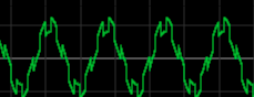 Suppose you have a temperature sensor that puts out a tone from 250 to 300 Hz depending on the reading. The wires going to the sensor are long and you find that you are picking up 60 Hz hum from the AC wiring. Your input signal might look something like the one on the right. The 60 Hz hum is about 5 times a strong as the square wave data signal. How can you recover it?
There are several answers, of course. But if you observe that both the positive and ground wire going to the sensor will pick up the hum, a good answer is to subtract the return leg from the positive leg. Since the noise is the same on both wires, it should subtract out, leaving only the signal of interest. Here’s an example circuit for removing 60 Hz hum:
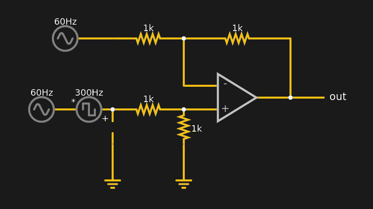
Here, the + terminal will be at 50% of the input signal. That means, by rule #2, that the – terminal will also be at that same voltage. Suppose there is a steady 2V on both inputs. The + terminal will then have 1V on it. That means the – terminal will also have 1V. If the input is 1V and the – terminal is 1V, the output must be at 0V since the feedback network will be like a voltage divider. No matter how the voltages change together, the output will remain zero.
But what happens if both inputs are at 2V and suddenly the input at the + side jumps by itself to 4V? Now the + terminal is at 2V, and this causes the current flowing to change (to zero, in this case). That means the output voltage has to change to set the same current in the feedback resistor. Since that’s zero in this case, the output must also be 2V.
If the zero current is confusing, try a different voltage like 3V in this circuit. When you flip the switch to feed 3V into the circuit, the + terminal because 1.5V so you have 0.5V across the input resistor, which means you’ll need the same current through the feedback resistor and the output will be 1V.
There are a lot more things you can do with op amps, but those will have to wait for a future Circuit VR. While modern op amps are great, they still aren’t perfect. The inputs will have a little leakage. The outputs will not get right up the rail if you draw much current from them in a general-purpose op amp. If you are dealing with high frequency, you’ll need to carefully select parts. Precision circuits may need care for offset trimming and other special design considerations. However, compared to building precision amplifiers from bare transistors, having high-quality op amps is a real time saver.
There are many specialty op amps. Some operate on current inputs. Some have special output stages. For example, comparators are op amps with high speed output stages that tend to saturate quickly one way or the other. There are many choices depending on what’s important to your design. If you want some extracurricular reading on op amp architecture selection, Analog Devices AN-360 is a good overview of the subject.
Circuit VR: Even More Op Amps
Source: HackADay